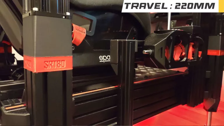
The SRT80 are actuators based on 80ST servo motors, 80×80 aluminum profiles, and a special ballscrew that allows a travel of 220mm (compared to about 130mm for the OpenSFX).
For each step, there is a dedicated channel on the Discord to help you (go to SRT80 ENGLISH after choosing the language in verify-first.
Summary :
- How to start
- How it works
- Shopping list
- Control Box
- Wiring
- Driver settings
- Arduino Code
- FlyPT configuration
- Simtools configuration
- 3D files
- Assembly
- FAQ
1) How to start
All the necessary documentation is available on this page. If you have any questions, the FAQ is there to answer them, and if you don’t find what you’re looking for, take a look at the Discord to find the whole community!
The SRT80s are very similar to the OpenSFX100 in their operation. The opensfx.com site is a source of additional information.
To succeed in this project, it is necessary to test your work at each step: the motors alone, the mechanism alone, then the two sets, then the whole on your simulator.
I reiterate the warning: Voltages, torques and speeds are important. Take all necessary precautions. I am not responsible for any problem.
2) How it works
The SRT80 actuators are based on a ball screw with a ball nut on it. The ball nut moves up or down as the screw turns. The screw is attached to the shaft of a motor called a “servo motor”. The servo motor is controlled by a driver. The driver receives instructions from the arduino which tells it how many degrees to turn (pulse), and in which direction (dir).
It is the FlyPT software that retrieves the data from the game, and sends it to the Arduino.
The servo drivers are activated by the Arduino board. Once activated, the drivers emit a very slight aïgu noise, noise covered by the general operation of the simulator.
3) Shopping list
The shopping list is available here. The kit proposed by Industry&CNC is proposed in economic delivery for Europe (delivery by train, indicated by “seller’s shipping method”). This shipping method takes about one month (do not take into account the Aliexpress estimate). Please note that the tracking number provided by Industry&CNC will only be functional at the end of the transport.
Moreover, do not hesitate to contact me if the rates or the shipping costs are aberrant. We tried to offer the best rates on all means of delivery, but there may remain some errors related to the system.
The shopping list is separated in two parts: the first one indicating what is included in the kit, and the second one what is not, and must be ordered separately.
It gives the details of the parts needed to manufacture a cylinder. Industry&Cnc offers a discount on most of the items when you buy 4 of them.
“What is the difference between the A and C drivers?” Unlike C drivers, A drivers emit a high-pitched noise when they are active. This high-pitched noise is covered by the operation of the simulator.
4) Control Box
The control box which houses the arduino is available in several versions:
| Standard Control Box | Smart Control Box (Patreon exclusivity) | Competition Control Box |
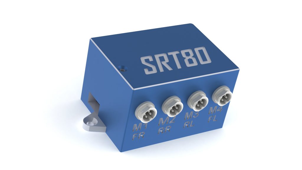 | 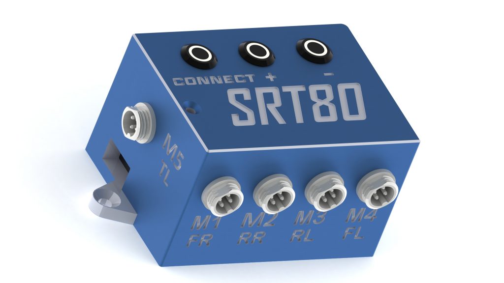 | 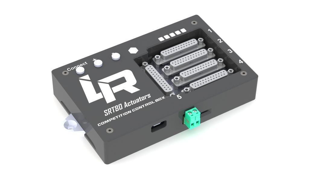 |
| 4 actuators | 4 actuators + TractionLoss 3 buttons Feeback LED : connection, error. | 4 actuators + TractionLoss 3 buttons Feeback LED : connection, error. Plug & Play Emi Shielding |
| Complete documentation | Complete documentation | Complete documentation |
5) Wiring
Caution : Voltages, torques and speeds are important. Take all necessary precautions. I am not responsible for any problem.
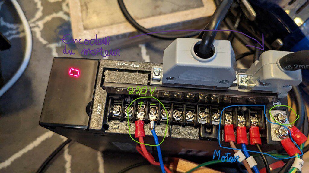
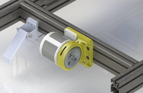
a) Driver and motor power supply
It is difficult to make a mistake in the wiring of the motor. This part is detailed on page 8 and 13 of the drivers manual.
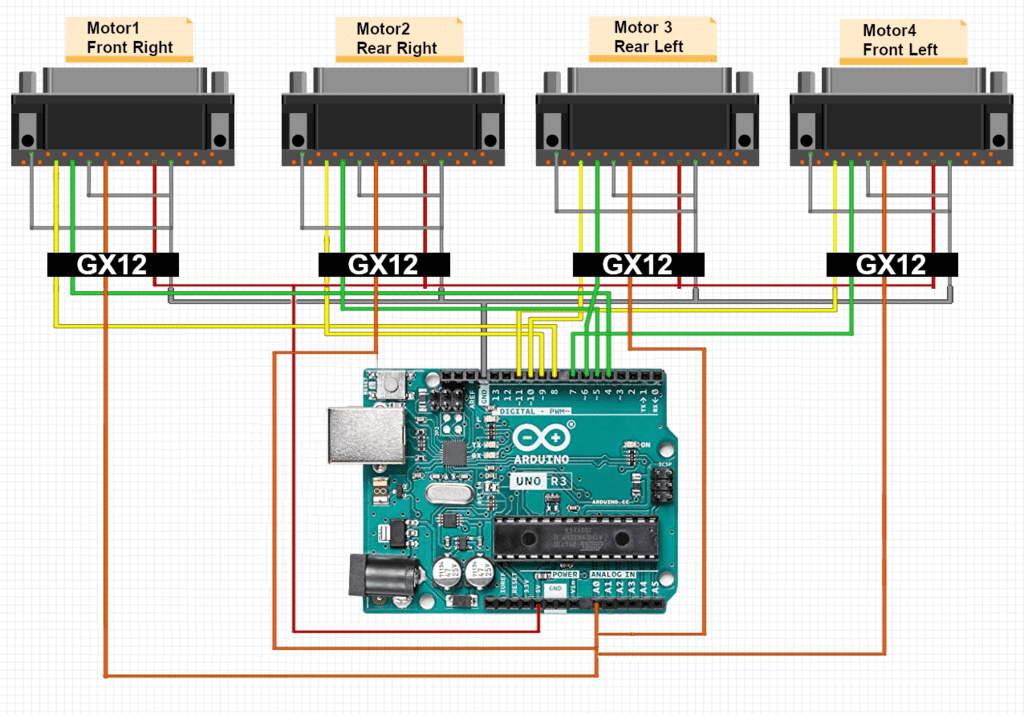
b) Wiring between Arduino and driver
We reuse the pulse/dir connectors on the DB25 socket of each driver. On the arduino side we use a 5 pins GX12 connector.
| Motor 1 | Motor 2 | Motor 3 | Motor 4 | DB25 PIN | |
| STEP | 8 | 9 | 10 | 11 | 3 |
| DIR | 4 | 5 | 6 | 7 | 4 |
| ENA | A0 | A0 | A0 | A0 | 6 |
| 5V | 5V | 5V | 5V | 5V | 9 |
| GND | GND | GND | GND | GND | 5, 10, 14 |
Schematic :
| Arduino | Driver (prise DB25) | |
| Pulse | D8/D9/D10/D11 | pin 3 |
| Direction | D4/D5/D6/D7 | pin 4 |
| Enable | A0 | pin 6 |
| 5V | 5V | pin 9 |
| Masse | GND | pin 14/5/10 (the three pins of each DB25 must be connected to ground) |
For info: pin 13 of the Arduino is also a mass thanks to the code.
6) Drivers settings
The drivers, similar to AASD, have 200 parameters, fortunately you don’t need to change them all.
They are detailed on page 38 of the manual. This video shows how to modify the parameters.
I highly recommend testing the motor operation via flypt with the engine disassembled!
| Parameter | Value | Explanation | Comment |
| Pn001 | 4 | Select the right motor, in this case an 80st-M02430 | No need to use a more powerful motor |
| Pn002 | 2 | Motor control mode | 2 : position mode |
| Pn003 | 0 | Activate/deactivate the driver | 0: the driver is turned on by the arduino. 1: the driver is always on |
| Pn008 | 300 | Torque limit | |
| Pn009 | -300 | Torque limit | |
| Pn051 | 1200 | Maximum motor speed | This parameter manages a little the “violence” of the simulator, thus to increase with parsimony |
| Pn098 | 6 | Pulse multiplier | Do not put another value! |
| Pn109 | 1 | Filtering parameter | See the manual |
| Pn110 | 30 | Filtering parameter | See the manual |
| Pn113 | 20 | Filtering parameter | See the manual |
| Pn114 | 10 | Filtering parameter | See the manual |
| Pn115 | 15 | Filtering parameter | See the manual |
7) Arduino Code
At this stage, you have your motors wired to the Arduino, without the reste of the mechanical parts. You can flash the Arduino code that is specific to your Control Box (how to flash a code).
We will be able to test the connection between the arduino and the software you are using (Flypt or Simtools). Once the connection has been verified and the motors tested, you can move on to assembling the mechanics.
8) FlyPT Configuration
All the electronics are ready: Arduino flashed and connected to the drivers, configured drivers, and connected motors, without the mechanical part.
You can now load the dedicated FlyPT profile.
To load the FlyPT profile, launch FlyPt (v3.4.2), right click>file>open and select the profile.
To finalize the installation, click on the “Output::serial” tile, then on “update ports” and in the “port” list select the arduino port. Then click on ” connect “. The motors are all supposed to turn in the same direction smoothly and then stop: this is the simulator that starts from the bottom position to the middle position. Now click on disconnect, and the motors perform the same movement in the other direction: the simulator moves from the middle position to the bottom position. If everything went well, you can continue. Otherwise, see you on the Discord.
Now in the main menu, click on the tile of the simulation of your choice, then click on connect, and check if the motors are reacting to the games inputs.
The FlyPT website contains documentation that you should read if you want to take advantage of it : each game need a specific configuration
Once you have your actuators working and your installation is running smoothly, I also recommend watching this video to understand how to use the filters.
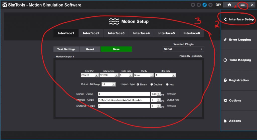
9) Simtools Configuration
Here is the configuration for Simtools V3
And here is the assignment of the axes:
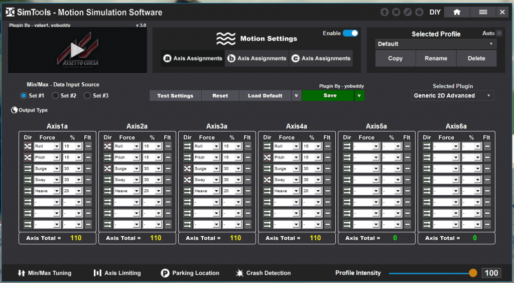
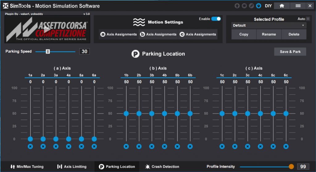
You can launch the game and check if the behavior is as follows:
1) All motors rotate in the same direction at start-up (the simulator moves from the bottom position to the middle position)
2) In game, the engines seem to follow the movements of the car
3) When you leave the game, the actuators perform the opposite movement of 1), the simulator goes from the middle position to the bottom position.
If the behavior is ok, continue with the assembly
10) 3D files
The 3D files are available on the download page.
If you don’t own a 3D printer, you can order them here.
You will also find a step file which will allow you to integrate the actuators in your CAD.
Each file contains a printing instruction in the form xx-xx. The first number is the precision, the second the filling. For example 02-30 means accuracy of 0.2 and filling at 30%. It is also useful to double the thickness of the walls.
The mention “support” indicates that supports are needed…
I also recommend to activate the adhesion to avoid warping (part that comes off the support).
I recommend using the Cura slicer.
All the parts are in the ideal orientation for printing.
The box containing the Arduino is available separately here.
9) Assembly
10) FAQ
My electrical installation is in 110V, what to do (ex : Canada)
A priori the servos are designed to work with 220v. You can buy a 110v>220v converter (Amazon), or set the drivers to accept 110V, at your own risk of course.
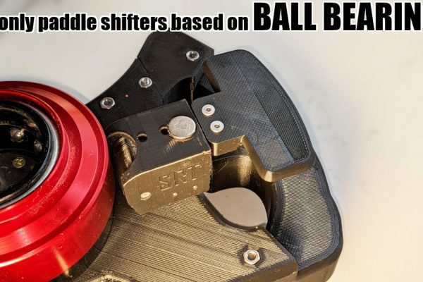
Can I use this actuator in Push-Pull mode?
Yes, just screw in a 22mm ball joint like a POS22.
Why don’t I see any information about the emergency stop button?
Basically there are two failures that can occur: either the motor starts to turn endlessly in one direction, or in the other. In one case, the slider comes to a stop on the linear bearing support, and blocks the motor: no dramatic consequences. In the other case, the slider can break the linear bearing support, then come out of the rod. This is less funny. The problem is that the motor is so fast that you probably won’t have time to cut… That’s why I don’t usually include it in my setups.
Why an Arduino Uno instead of the Leonardo used on the OpenSFX?
Because the Uno is cheaper, easier to find, and also because it has a USB type A connector that is more resistant than the micro USB of the Leonardo. Moreover, the computing power is the same.
Is the SRT80 compatible with Thanos controller ?
Yes.
How can I prevent my chassis from jumping when making big movements?
The actuators are powerful enough to make the chassis jump. You need to limit the speed of the actuators or secure them to the floor.
FlyPT or Simtools?
I personally use FlyPT and prefer it because its presentation is more logical (although confusing at first), and it’s much easier to see what’s going on. Furthermore, it is much more practical to share a FlyPT setting than Simtools. That said, Simtools is more popular, its Simtools community established, support is responsive, and software development is very supported. In both cases your experience will be excellent.
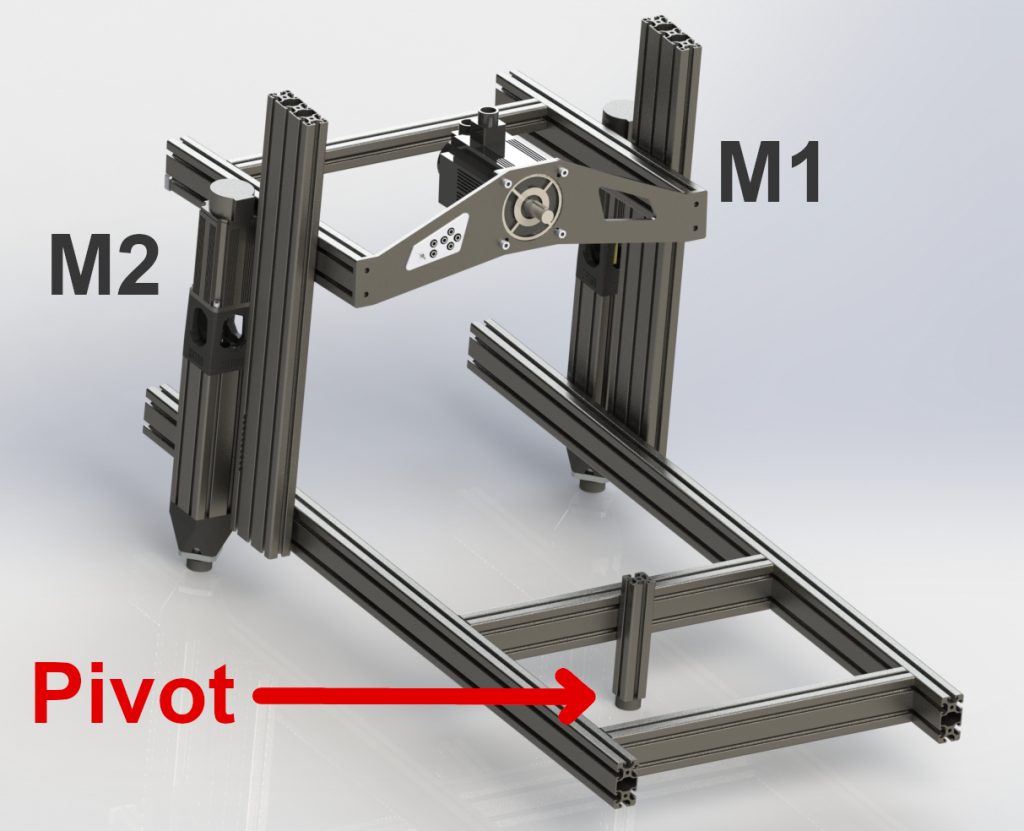
2-actuators configuration?
The 2-actuators configuration allows you to obtain a high-quality 2DOF simulator, and to limit the expense before adding the 2 other actuators. To do this, you’ll need a pivot positioned at the center of gravity. A shock-absorbing foot will do the trick nicely. The two actuators are positioned at the front. M1 is the right front, M2 the left. You can then use this specific FlyPT profile.
3-actuators configuration?
The 3-actuators configuration is not recommended: it does indeed produce a 3DOF, as with 4 actuators. But the triangular positioning of the actuators makes the chassis unstable and prevents you from taking full advantage of the actuators’ power. It also means that the “middle actuator” has to be positioned quite a long way in front or behind, which reduces angular travel.
Hi, Thanks for this.. Im planning to build this one.. 🙂
But can i ask, what do you mean?
“Caution : Voltages, torques and speeds are important. Take all necessary precautions. I am not responsible for any problem”
Can you please explain more? Or Which part on build process should i concern this?
Thanks
Actually, if you follow the steps, there isn’t so much risk because in the worst case, you will have the motor rotating at high rates…alone. But of course if you put yours fingers in the wall plug, I won’t be responsible.
Haha that is funny, thank you so much for the response.. Godbless
Do you have a price list for your parts with approx shipping costs to USA. looking to build for 3 or 4 complete actuators , and electronic for Thanos my 8020 rig also I intersred in the belt system. Great ideas, thanks for your work.
Hi ! Sorry for the late reply.
You will have to check the detailled shopping list and calculate the cost by yourself.
Hello and congratulations on the project.
I’ve already built a 3DOF, which works very well but I’m not 100% satisfied.
Browsing the net looking for information, I first came across FSX100 and then your project, which I chose as my next reference for the construction.
On April 1st I ordered the kit for 4 srt80s which I hope will arrive soon. In the meantime I have already made all the necessary prints, with PLA-CF for greater strength. I was also looking into figuring out Flyptmover, but wanted to ask, since you keep the same connections on arduino as the original SFX100 project, if it would be possible to use SimFeedback instead of Flyptmover.
Hello from beautiful Italy, and thanks in advance
Ruggero
Hey ! Thanks for your message !
I guess we can use other softwares but i never tried..
Hello!
I Like your actuator, now Im inquiry in this world. I would like to ask, a few thing, if it is possible.
1) How you connect the Arduino to the PC? with the USB cable that you use for programming?
2) As i seen in your Arduino program, it is written for 4 actuator. Is it usable for 3 actuator without any changes?
3) As i saw in your videos, you are using 3 actuators, am i right? Which is better for a beginner, a 3 or a 4 actuator layout?
thanks all!
hey !
1) Yes, it is the same cable.
2) and 3) It should be possible to use just three of them, but i won’t recommand it, as the rig will be far less stable.
Thank you for the reply!
Now, as i said before, reading may things before, and i found a cnc driver unit.
Its name is: NVEM CNC controller. It has ethernet communication with high speed data transfer, and can manage 6 motors.
What do you think, is it worth to give a try to drive the servos with this, or the sim rig doesn’t require this stuff, and the well known Arduino is way enough and stable for this application? The board is about 100Eur on Ali.
Regards, levente
Hi, I have 2 questions
-currently i’m in the ordering process and Industry & CNC offers a Drivers A or C kit. What is C Driver, can it also be used ? Does it make less noise ? A B Driver is not available anymore.
-Do you plan a 5DOF conversion with Traction Loss ?
Anyway thank you for your projects , the gearbox rocks 🙂
Driver C does less noise. I’ll send a message to I&C.
Traction loss, yes in the future. You can already order a 5th actuator if you want 🙂
Hello Lebois!
You have amazing projects, and I’d like to create some myself. I’m even getting a 3D printer. I’ve also started ordering the Srt80 actuators for a 6DOF system with Thanos controller. Please let me know if this is madness or if it’s feasible. Thanks for everything; you’re the best.
yes it is 🙂
Thank you for your response. Does it make sense to purchase servo motors with brakes when using vertically mounted actuators? I was thinking it might come in handy in case of a power outage or to prevent the risk of them falling. Thank you.
that’s not necessary
Thank you for your response. If it’s not necessary, I don’t want to incur unnecessary costs. I’m currently trying to order the first 4 pieces, but PayPal is quite problematic. What do you think about payment through AliExpress? Will I encounter any issues?
No you won’t… I order a lot of stuff on Ali.
Thank you.
Dear Lebois,
I ordered the SRT80 actuators with the white (noiseless) drivers. Now they are here and Im not sure how to connect the 220V cable. In your picture with the normal (black) drivers there is 1 red cable to L3 and 1 blue next to it (cant see the name of the port) and T, Circle, P+ ports. In the white drivers I have only L1, L2, L3, C and P ports. I assume the red should go to L3 but where I should connect the blue port? To C? The yellow/green cable is clear 😉
BR Michal
I’m on way back home now. Can you post on discord with pictures?
OK, thanks for your answer. I will post the subject today on discord with pictures and also with a question for the EMI Filter connection. Come good back home mate, you are doing awesome stuff for the SIM Racing Community here!
BR Michal
Good morning,
I would like to make an SRT80 kit, but I was wondering if the control box you sell replaces the Arduino?
THANKS
Yes it does.
Please please please show a diagram or send me one regarding 110 V connection versus 220 for the servo driver. I need to know ASAP as I’m putting my order in on the first. I would really appreciate it. I’ve seen one video that shows you can connect to 110 under a certain parameter that you have to change. I didn’t see the actual physical wiring on your diagram/picture
Wiring is the same, please check the faq